
Click the above photos for details.
The latest Android application I’ve written is called "PICFTDI.” This simple-to-use app features:
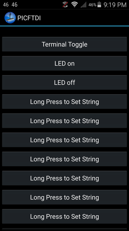
- 24 buttons to control your microcontroller with a press of the button (see Photo #1)
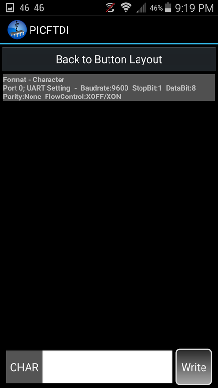
- Ability to send/receive data to/from the PIC32 MCU via chat-like terminal view layout (see Photo #2)
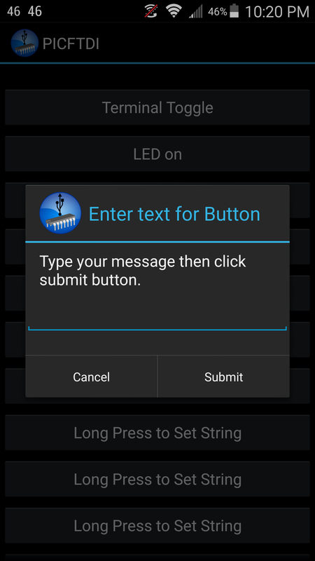
- To change the string, simply long-press any of the buttons (see Photo #3) or use the chat like terminal view to type any string you would like.
- App auto-launches when PIC32-based boards are connected
As a USB application, the PIC32 microcontroller board must be connected to an OTG-supported phone or tablet using an OTG USB hardwired connection. Also note that this will only work with PIC32 boards that have FTDI_USB-to-serial chips. PIC32 boards without FTDI_USB-to-serial chips are currently not supported in this app, see my other app "PIC32USB" that supports PIC32 boards that have a direct USB connection to the D+ and D- pins on the microcontroller with no other chip in between. In addition, note that no extra shield or code libraries are required. All you need to use is Serial.begin(9600).
I created this app to allow anyone to create fun and unique projects using a hardwired connection from an Android phone/tablet to a PIC32-based board. For example, what if you wanted to password protect a drawer, keeping it locked while you (and your Android device) were away, and unlocking it only when you plugged your Android into your PIC32-based board and the correct password "string" is sent to the PIC32? That's just one example of a cool way to use this app.
Now let's get started:
Note that the code example below is the same as the code example file at the bottom of this post.
Items you will need:
- PIC32 microcontroller
- OTG USB cable
- OTG supported Android device
Link for standard OTG USB cable found on Amazon:
http://www.amazon.com/s/ref=nb_sb_noss?url=search-alias%3Daps&field-keywords=otg+usb
Link for power OTG USB cable found on Amazon:
http://www.amazon.com/s/ref=nb_sb_noss_2?url=search-alias%3Daps&field-keywords=otg+usb+power&rh=i%3Aaps%2Ck%3Aotg+usb+power
The main difference between the standard OTG USB and the power OTG USB is that the standard one will use your Android device to power the microcontroller and should be limited to around 200mA. If you used the power OTG USB you can provide an external power source such as your factory charger or a power bank to provide more current if needed for the microcontroller and its components.
Link for power bank found on Amazon (optional):
http://www.amazon.com/s/ref=nb_sb_noss_2?url=search-alias%3Daps&field-keywords=power+bank
// Microcontroller code example
String inputString ="";
char incoming = 0;
void setup ()
{
delay(15);
Serial.begin(9600);
delay(50);
pinMode(PIN_LED1, OUTPUT);
digitalWrite(PIN_LED1,LOW);
//Add pinMode for LEDs here, etc
}
void loop ()
{
if(Serial.available()>0)
{
while(Serial.available()>0)
{
incoming = Serial.read();
delay(4);
inputString += String(incoming);
}
//must be exact spelling, no extra spaces
if(inputString == "LED on")
{
digitalWrite(PIN_LED1,HIGH);
delayMicroseconds(1);
Serial.println("LED is now on");
//add code here
}
if(inputString == "LED off")
{
digitalWrite(PIN_LED1,LOW);
delayMicroseconds(1);
Serial.println("LED is now off");
//add code here
}
}
inputString ="";
delay(50);
}
Please note: Due to the hardwired connection to the phone or tablet, this application is use at your own risk. It is recommended to use an OTG USB cable that allows an external power source if you are drawing more than 200mA of current from the device. Be careful to never create a short from power to ground since you have the potential of damaging your USB connection on your device. I have extensively tested this with most of the available PIC32 microcontrollers that have a FTDI_USB-to-serial chip. If using an OTG USB cable that allows an external power source it is recommended to only use the factory charger that came with the phone or tablet as the external power source.
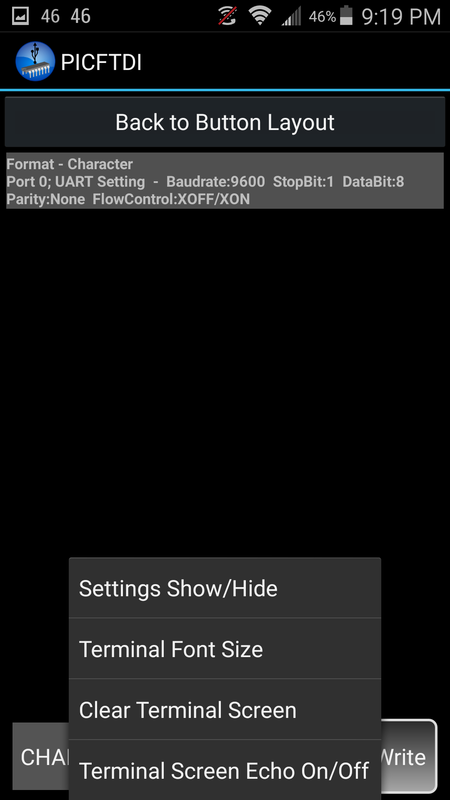
This application defaults to a baud rate of 9600, but you have the option to choose from a variety of other baud rates. Using the settings menu option while on the terminal view layout you can select up to a 921600 baud rate. Note that depending on your microcontroller some speeds may not be recommended.
This will only work with PIC32 boards that have an FTDI_USB-to-serial chip. My other app called “PIC32USB” supports PIC32 boards that have a direct USB connection to the D+ and D- pins on the microcontroller with no other chip in between, see this link http://www.dare2tech.com/pic32usb.html
Thank you for checking out this application
Below is a basic program that can be used, a very simple one for a basic proof of concept. The PICFTDI_Demo_Simple file should be able to be loaded and programmed on any PIC32 board that you have without modifications.
| picftdi_demo_simple.pde |
Google Play Link: https://play.google.com/store/apps/details?id=com.gardnertech.picftdi
There are 5 more example program files that can be used and modified found in the following link below.
http://www.dare2tech.com/electronics/bluetooth-hc-05-or-hc-06-tutorial-with-pic32
http://www.dare2tech.com/electronics/bluetooth-hc-05-or-hc-06-tutorial-with-pic32