This is a short overview of the components used to make yourself a remote controlled car using a PIC32 microcontroller.
Have you ever wanted to make and control your own car, see below for the components used. In the future I will go over an in depth tutorial with schematics of the connections.
Items used:
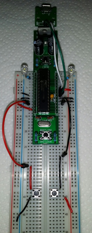
Most of the items used I found on eBay for fairly cheap. The power source I used was a 5 volt 10,000 mAh power bank that was then boosted to 6 volts using the step-up module which would power the car for several hours of fun. Seen in the video and photos I used my MAKEmicro32 microcontroller board seen plugged in the breadboard.
See my contact page to request the code I used or if you would like me to put together the in depth tutorial with schematics for a guide to connect everything together.
Have you ever wanted to make and control your own car, see below for the components used. In the future I will go over an in depth tutorial with schematics of the connections.
Items used:
- PIC32 microcontroller
- Power source
- L293D Push-Pull 4-Channel Driver
- XL6009 Step-up module
- Four Arduino wheels
- Breadboard
- Several jumper wires
- Some rubber bands
- Some cardboard
- My PIC32BTN Android application
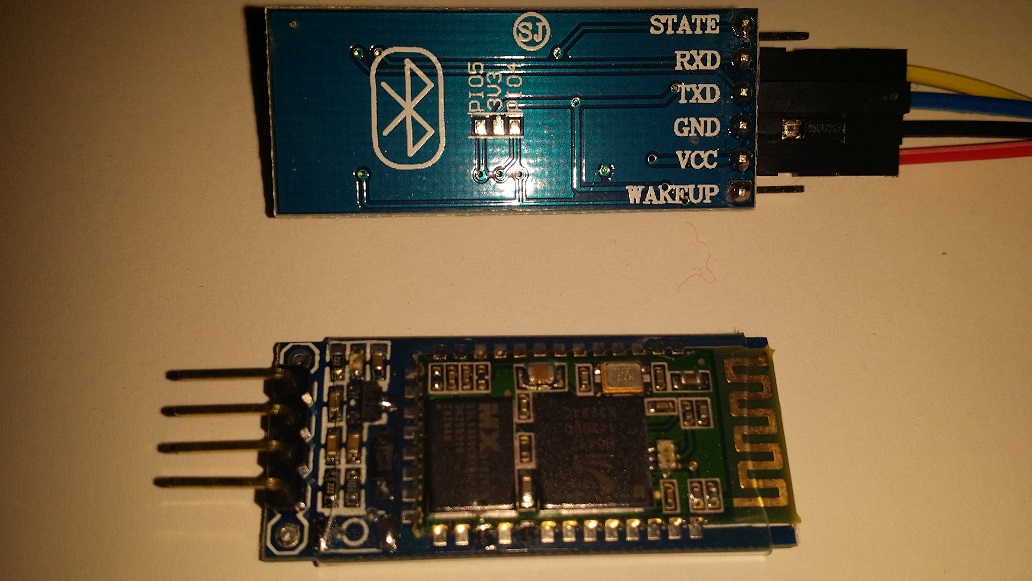
- HC-05 Bluetooth Module
Most of the items used I found on eBay for fairly cheap. The power source I used was a 5 volt 10,000 mAh power bank that was then boosted to 6 volts using the step-up module which would power the car for several hours of fun. Seen in the video and photos I used my MAKEmicro32 microcontroller board seen plugged in the breadboard.
See my contact page to request the code I used or if you would like me to put together the in depth tutorial with schematics for a guide to connect everything together.

 RSS Feed