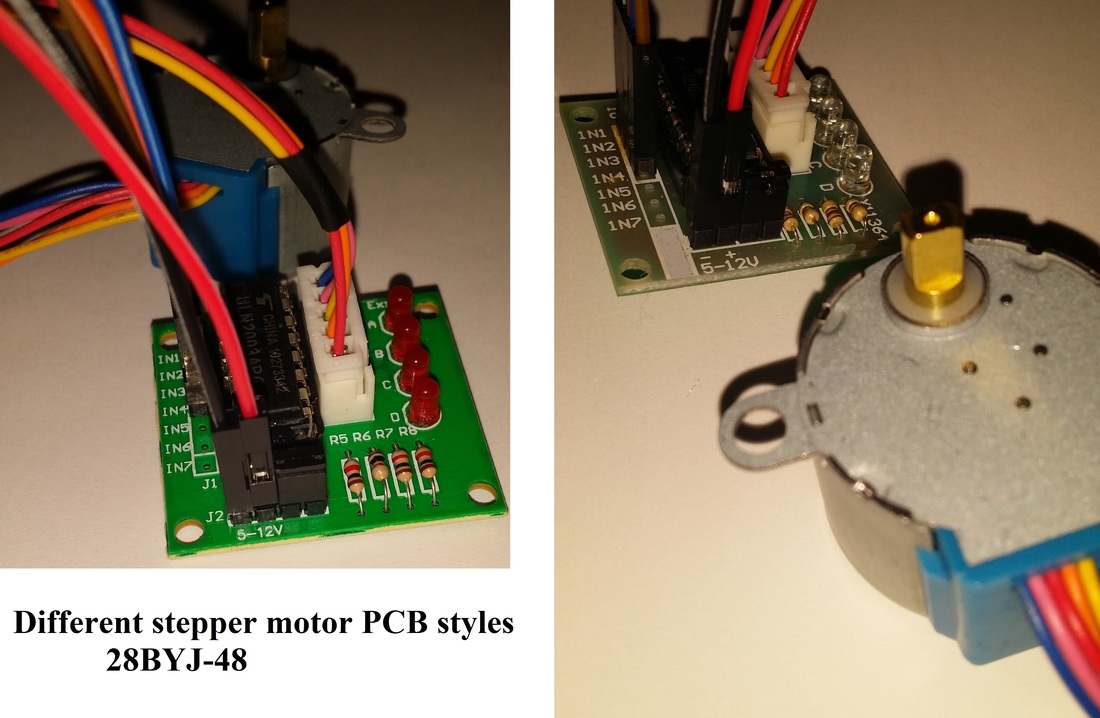
This is a simple starter tutorial for the 28BYJ-48 stepper motors as seen in the pictures above which may come with different looking PCB’s, but function the same.
Materials used:
1) One Microcontroller (PIC32MX250F128B)
2) One 28BYJ-48 stepper motor with ULN2003 PCB
3) Four jumper wires (male to female)
4) Two jumper wires (female to female)
5) Power source (10,000 mAh power bank battery pack 5volts)
The power bank is optional and can be switched out with any 5 volt power source and the jumper wire connection style may vary depending on the connectors available on your microcontroller board to make the necessary connections. You will want to be sure that the power source can provide well over 200mA or 0.2amps since it will be required for the stepper motor and your microcontroller current requirements.
For the code examples attached I used the digital pins 13,12,11,10. You can use any digital pin, just make sure you change it accordingly in the code example attached if you do. This was put together using MPIDE for PIC32 microcontrollers, but the code will work with Arduino or similar microcontrollers as well.
Connections between the microcontroller pins to the stepper motor PCB are as follows:
Stepper motor PCB <----to----> PIC32 Microcontroller Pin
IN1 <--------------wire------------> 13
IN2 <--------------wire------------> 12
IN3 <--------------wire------------> 11
IN4 <--------------wire------------> 10
The plus sign on the stepper PCB will be connected to 5 volts (red wire in front on photos) and the minus sign will be connected to ground (black wire in front on photos). Also, depending on the stepper motor PCB the plus sign and minus sign might be located behind or in front of the pin connectors.
On the stepper motor PCB make sure that there is a jumper on the two pins closest to the resistors as seen in the photo near the 5 volt input connection. Sometimes depending who you purchase the stepper motor from, the jumper might be missing, the jumper is needed in order for it to function (the black jumper/connector seen in photo).
If you’re interested in a detailed video explanation of how stepper motors work, I recommend this one: http://bit.ly/1MeFP7N
| stepper_motor_tutorial_simple.pde |
| stepper_motor_forward_then_backward.pde |
| stepper_motor_tutorial_no_delay.pde |
Direct video link: https://youtu.be/EOM6aipshaI
 RSS Feed